Getting into FPGAs - Quick-start guide for the EP2C5 Cyclone II Mini Board
Getting into FPGAs with a super cheap board

There are a good number of cheap, small fpgas available around on ebay now, but lack sufficient documentation on how to set up the tool chain and get programming. This guide hopes to give a quick way into the world of fpgas.
Windows only I'm afraid! Good luck trying to get drivers and the software to work in wine.
Original guides and some pictures from the great resource
fpga4fun.com
Where to buy
There are a wide range of suppliers that you can get the board I will be documenting. I managed to get my EP2C5T144 altera minimum system learning development board from here. Make sure you get a USB blaster as well!

The board has two interfaces in which to program it - the JTAG and ASP ports. Luckily, the USB blaster is capable of both protocols and we will be using them both!
Software and Drivers
You'll need to download Quartus II 11.0 (service packs optional) and ModelSim (also optional, but simulating stuff is quite useful) from Altera's website. As of writing, none of the download links work but luckily I found copies on Altera's ftp site:
- ftp://ftp.altera.com/outgoing/release/11.0sp1_quartus_free_windows.exe
- ftp://ftp.altera.com/outgoing/release/11.0_modelsim_ase_windows.exe
After installing (it can take quite a while), if you plug in your USB blaster, it will most likely not be able to find the device driver. Quartus II comes with the drivers, but they are not signed so windows will not allow them to be installed!
There are a few places where people claim to have signed the drivers themselves if you want the easy route, but the (somewhat) safer route is to disable driver signing and install the official altera drivers.
Create a batch file to disable driver signing and copy in this code
BCDEDIT -Set LoadOptions DISABLE_INTEGRITY_CHECKS
BCDEDIT -Set TESTSIGNING ON
and another to re-enable driver signing
BCDEDIT -Set LoadOptions ENABLE_INTEGRITY_CHECKS
BCDEDIT -Set TESTSIGNING OFF
Run the first as an administrator to disable driver signing and reboot.
Now, plug in the usb blaster and open up device manager. Find the device and manually find driver software. Assuming you installed Altera Quartus to the default location, set windows to find the drivers in C:\altera\.
Making your first project
-
Boot Quartus II and click new project wizard
-
Choose a project director and name, click Next
-
Don't add any files (unless you already have pre-existing code you'd like to import), click Next
-
Set the family to Cyclone II and find the device in the list that matches your board (likely EP2C5T144C8), if you want to add in modelsim, click Next and then under ModelSim-Altera point it to
C:/altera/11.0/modelsim_ase/win32aloem, otherwise, click Finish ( you can change this later from the Tools -> Options menu) -
File -> New, choose Verilog HDL file
-
Add some code (such as:
module ledblink( input clk, input button, output LED, LED2, LED3 );

reg [26:0] cnt;
always @(posedge clk, negedge button)
begin
	if(~button)
		cnt <= 'b0;
	else
		cnt <= cnt + 1;
end

assign LED = ~cnt[24];
assign LED2 = ~cnt[25];
assign LED3 = ~cnt[26];
endmodule
- Save the file as ledblink.v (or whatever suits you)
- In the top-left pane, click on the Files tab. Your created file should be there. Right click and select
Set as Top-Level Entity(or Ctrl-Shift-J) - Now we can begin synthesis, Processing -> Start -> Start Analysis & Synthesis (or Ctrl+K)
- No errors should be reported
- Now we can assign the pins, Assignments -> Pin Planner. At the bottom, select the locations of the inputs and outputs. You can see the pins I went with (which are already connected to the onboard LEDs, switch and clock) in the picture below. You can then close that window.

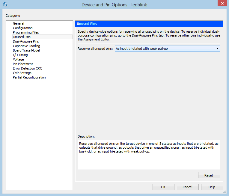
- It is suggested to set the unused pins to be tri-stated (effectively disconnected). To do this Assignments -> Device, then click "Device and Pin Options", select "Unused Pins" and set them to "As input tri-stated with weak pull-up"
- Now we can fully compile, Processing -> Start Compilation
- No errors should be reported
Programming
-
Now double click on "Program Device (Open Programmer)"

-
Connect the USB Blaster to the jtag port of the fpga dev board
-
In the Programmer window, click "Hardware Setup", then select the USB Blaster from the list

-
Close that window and then click Auto Detect, nothing should really change but the bottom half of the screen should still show the EP2C5T144 in the JTAG chain.
-
Click "Start"
-
The program should now be on the fpga!
-
HOWEVER this code will not run accross power cycles, for this we need to program the onboard EEPROM chip!
-
Go back to your main Quartus window and go to Assignments -> Device
-
Click "Device and Pin Options"
-
Configuration, and ensure "Use configuration device" is checked and select from the drop-down box EPCS4

-
Click OK on the windows to get back to the main window
-
Re-compile the project as we have effectively changed the chip we are using
-
Open up the programmer window
-
Change Mode from JTAG to "Active Serial Programming"

-
This will produce a warning, Select Yes
-
Now click Add File and select the
.poffile -
The bottom pane now reflects the chip we are programming, make sure to select "Program/Configure" and optionally "Verify"

-
Click Start! This will take slightly longer to flash than the FPGA but all being well, restarting the dev board (by pulling power) after programming should result in a working project
For more info on integrating and using ModelSim, you can use this guide https://www.altera.com/en_US/pdfs/literature/ug/ug_gs_msa_qii.pdf, however some parts seem to not work entirely and I should really write a quick-start guide on that as well.