Digitising a 3 Manual Compton-Makin Organ: Part 3 - Replacing the electronics

AKA the fun part! I actually did this work almost 2 years ago now, but I never got round to writing it up until now!
I wanted everything to be controlled over MIDI, which is pretty much the standard way to communicate key presses, as well as stop changes and combination pistons on any sort of modern digital organ. This would also make it compatable with not only Grand Orgue (the software I had chosen to run my new organ), but Hauptwerk and other organ / piano emulators.
To achieve the MIDI connection, I did a lot of background research on different projects, and the one that stood out the most at the time was MIOS32 (http://www.ucapps.de/index.html?page=mios32_download.html). It could take in many, MANY, inputs and outputs simultaneously over a USB->MIDI connection as well as support for keyboard scanners if I wished to replace those in future. MIDI routing was also a cool thing it could do, so mapping different MIDI signals and channels through to other MIDI cables and the USB interface.
There was some development I found on an organ stop driver (for all the high power solenoids), but I ended up customising the design that was present on the MIOS32 website to suit my situation better. I needed approximately 96 solenoid outputs (each solenoid needs two outputs to push and pull each stop), a similar number of inputs for detecting the state of each stop as well as keyboard + toe pistons, and then MIDI connections to route in the existing keyboard + pedal scanners.
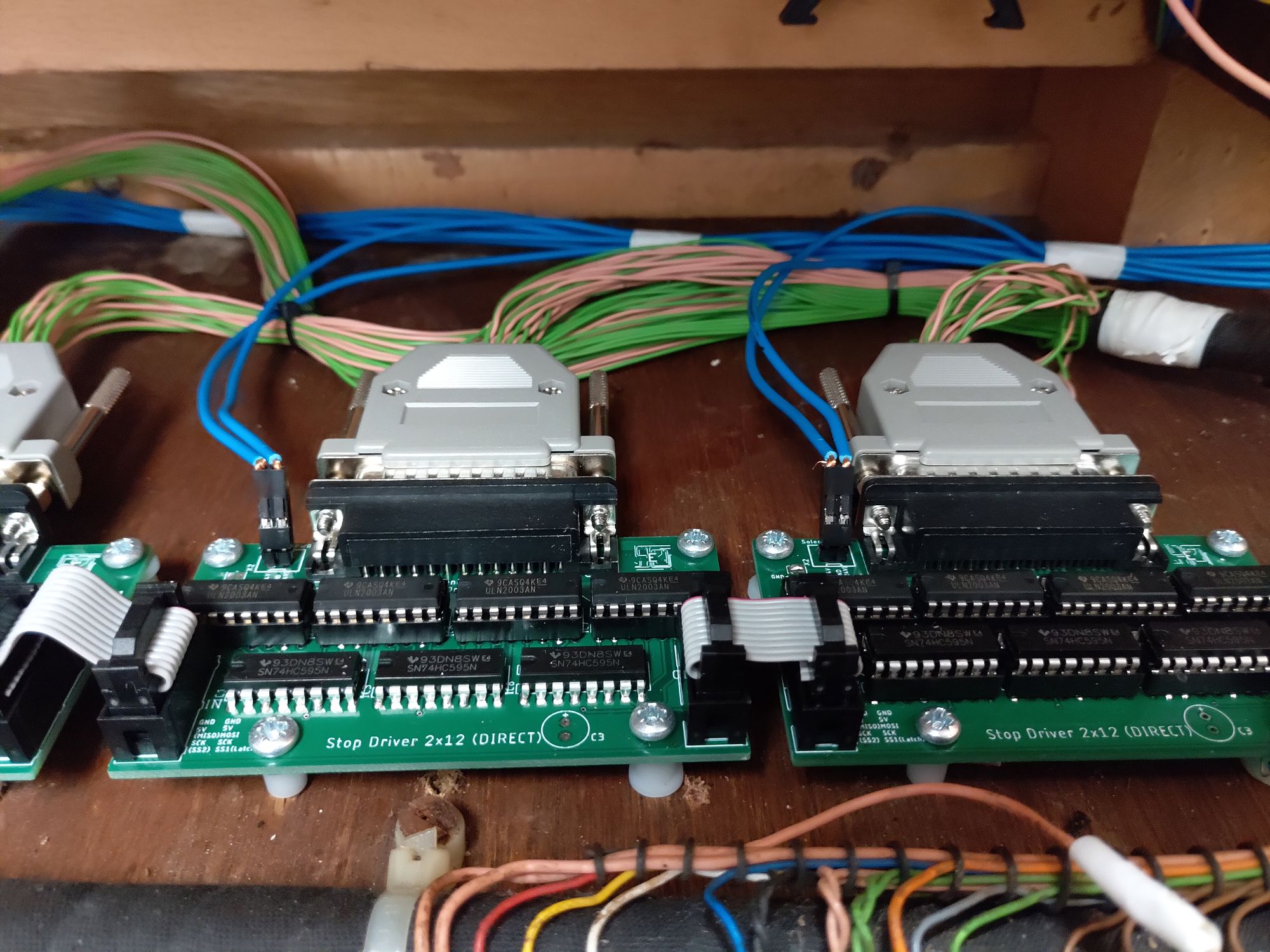
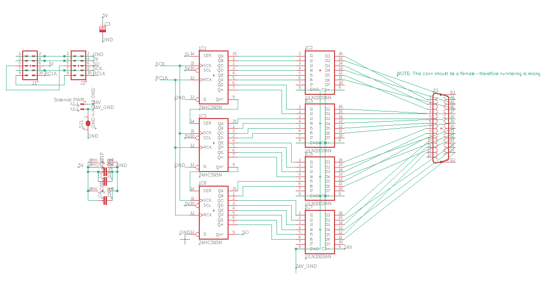
For the high power driving (the solenoids requried 24V at ~0.3A when driving, pulse length normally around 0.5s) I used ULN2003AN as research showed that other people sucessfully used these drivers (which have built in flyback diodes to a separate pin) for this exact purpose. The MIOS32 operating system talks to it's local GPIO via long strings of shift registers all scanned using DMA for a surprisingly high scan speed. I made a simple schematic allowing daisy chaining of multiple boards, and outputted the solenoid connections on DB25 connectors for simple maintenance. The dodgily crimped 2-pin headers were for the 24V and 0V supply for the solenoids from the beefy PSUs.
To make things simpler, I also re-structured the MIOS32 STM32 mainboard to have more parts that were available at the time. The DIN boards + MIDI input boards I believe were almost a carbon-copy of the existing designs, just redone to get customisable PCB size and it into Eagle, my preferred PCB CAD tool at the time.
All the combination pistons (buttons underneath or inbetween the keyboards) were already terminated on the connection strips at the bottom of the pictures of the organ on previous pages. Therefore all I had to do was connect these two header cable and ensure the pullups on the DIN board were working correctly. Funnily enough, I didn't realise until much later that the centre set of pistons on the keyboards (and pedals) were double-touch, meaning you could get one output for normal pushing, and then push harder to activate a second output (used for Great, and Pedal making a sort-of general combination button). These still haven't been fixed or wired in to anything as of April 2023!
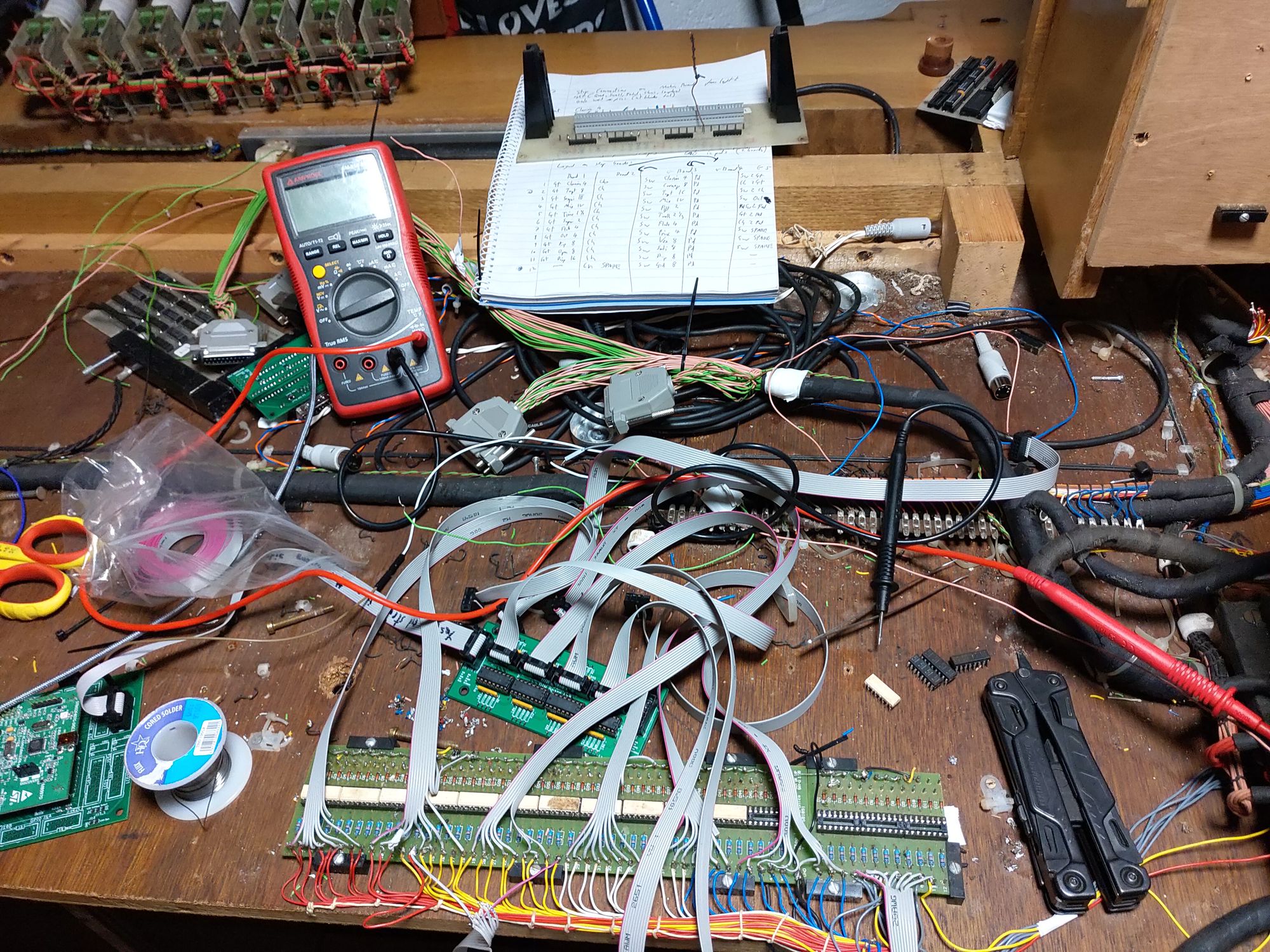
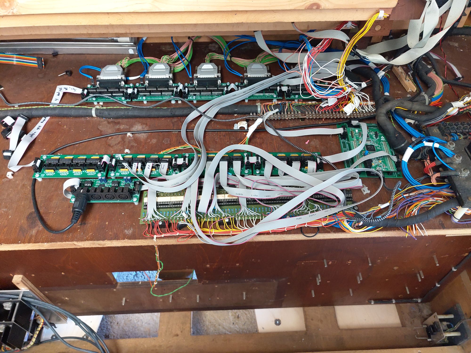
Below you can see a more finalised, and slightly tidier, version of this with all the DIN input boards allong the bottom terminating on 2x5 IDC connectors, the MIDI Input/Output board used for grabbing the keyboard scanner MIDI (the original from the organ, still a bit dodgy and crashes occasionally, I need to replace it), and the stop driver boards along the top.
There was some code additions I needed to make to the MIOS32 software, namely that my output boards would happily keep providing power to the solenoid if insturcted to indefinitely, making a rather toasty chip. To solve this, I re-wrote the DOUT code in MIOS to only output short pulses of ~0.5 seconds (iirc) when set high with a Note-On MIDI command (and likewise a different output corresponding to the inverse direction with a Note-Off MIDI command). Otherwise the outputs would be left floating. I attach what I believe to be my source code at the time of compilation - This should be a simple git commit or fork, but I clearly didn't check it out properly in Git at the time, and I haven't gone back across the code to tidy it up and split out my changes yet. There's also the .MIO config file that lives inside the STM32 to configure the routing of the MIDI and what Midi notes go to which place I think? (It's been a little while!)
Very exciting when I had the stops moving on their own once again, and such a satisfying sound. Ker-THUNK!