Digitising a 3 Manual Compton-Makin Organ: Part 2 - Initial Reverse-Engineering

So, after having moved the organ into its temporary (hah) home, it was time to look through the bits that were in the organ.
The manuals connected to this board with, is that really what it looks like, a MIDI connector! Well, digitising that part of the organ is already done! (Assuming it works... stay tuned to find out)
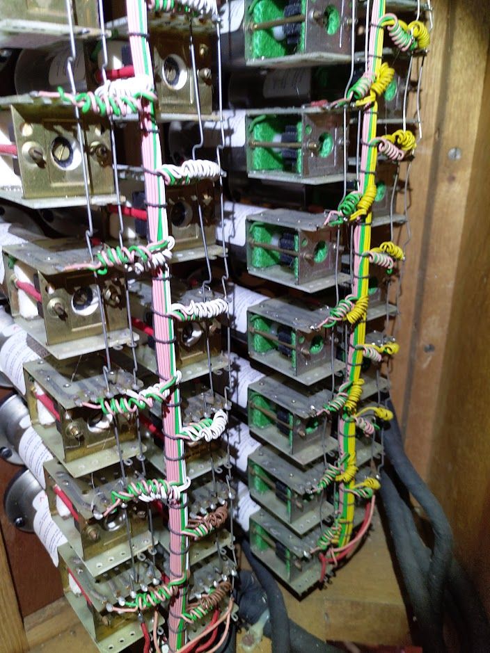
The wiring in the back of the stops on each side of the organ, sensing appears to be done by a magnet on the travelling bit of the piston with an output in the appropriate colour of the division it is controlling, and the other wide tied to positive voltage (I assume 5v). The solenoids are 24V, commonly tied again with the busbars going vertically, and the pink and green wire respectively for moving the stop in or out.
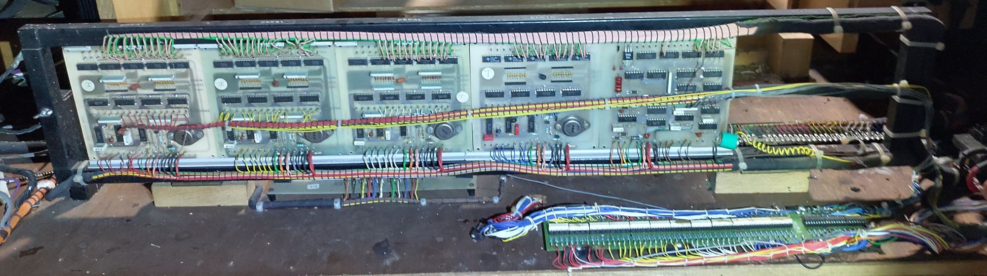
The large looms from these stop banks then come to a set of 5 PCBs held vertically in a metal cage behind the manuals. Ah-hah, something to actually reverse-engineer!
Just a side note at this point, I was aware that I was going to be ripping most of this out and replacing it, but finding out how it was originally constructed to work is something I find quite interesting, and also might provide some good tips on designing future circuits either for this project or for something else.
On closer inspection, 4 of these boards are the same, and the final one on the right is different. The number of connections at the top appeared to correspond to a board per section of the organ (i.e. Great, Swell, Choir, Pedal). The last board would then match up to being the couplers - hence a different board would be needed.
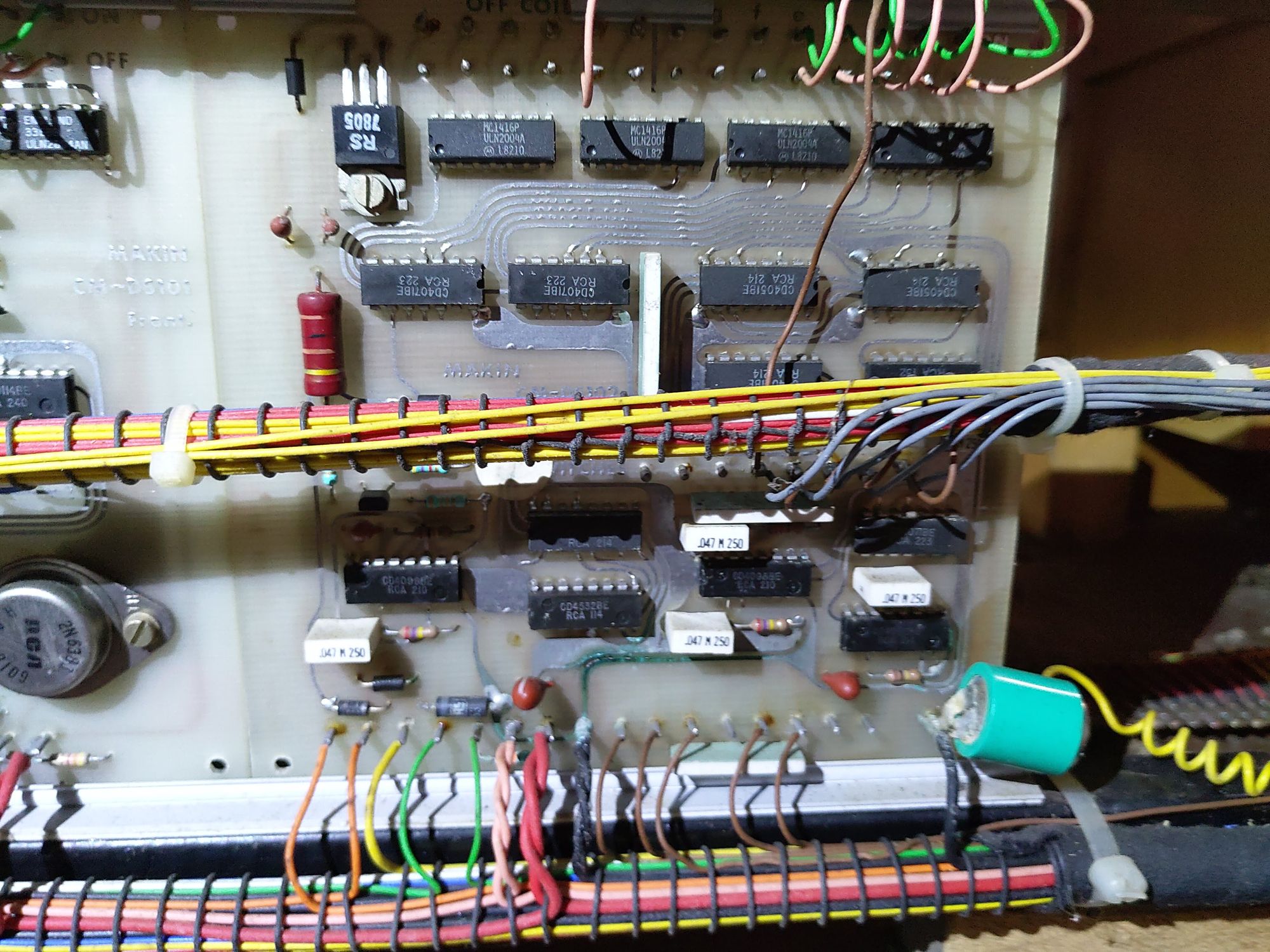
Above are the front and back pictures of a board if you want to try reverse engineering for yourself (for whatever reason). [EDIT: Re-posting this after my website went down, I can't seem to find the front/back photos at the moment. Let me know if you'd like them in the future and I can have deeper look]
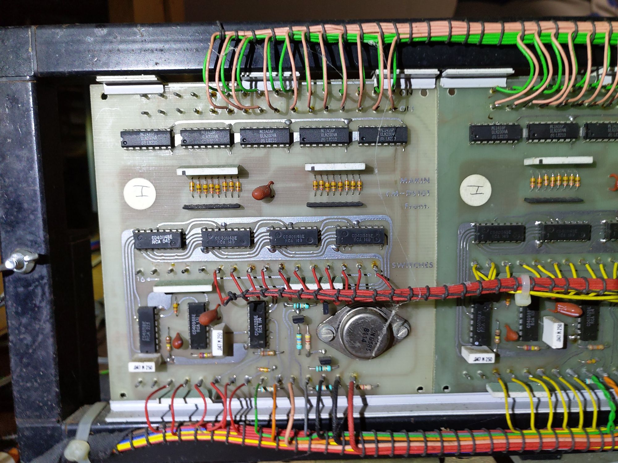
As I've already done the reverse engineering as I'm writing this post, I'll skip straight to the chase. The board is based upon a open-collector darlington pair driver ULN2004A driven by a set of battery-backed 40114 RAM chips. This is presumably how the saved-piston combinations work. The address is produced by a 4532 8-bit binary priority encoder, this appears to take in the 6 piston inputs from each manual (or pedals) and outputs it as a binary format.
The ULN200x series chips have built-in clamp diodes for driving inductive loads (for example the large solenoids connected to these), and have a seperate commoned emitter. This feature is specifically used on this board by setting up which solenoids need to be switched by the RAM, and then initiated as a big block tying the correct solenoids to ground through the chunky transistor. This timing is disciplined by 4098 monostable multivibrators. A very rough schematic I made for one channel of switching is below:

The last PCB appears to have all the same components in a different layout, I presume there is some logic to handle the toggle function of the couplers on the pistons as well as the standard piston combinations.
Audio Generation PCBs
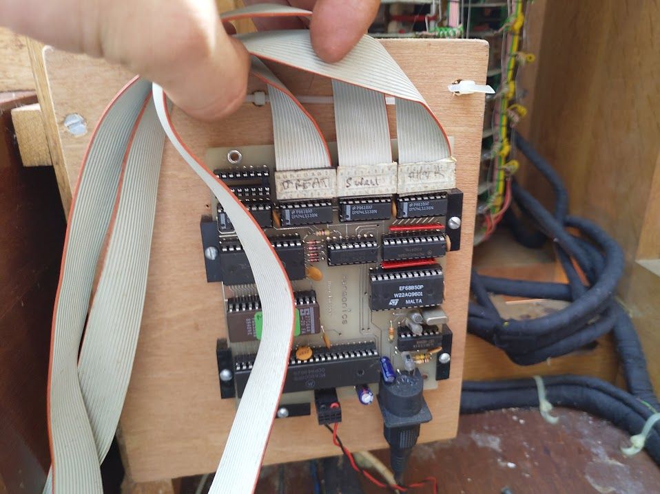
On the back of the organ, there is a flip out section of wood containing all the audio generation gubbins (apologies for the blurry overview photo).
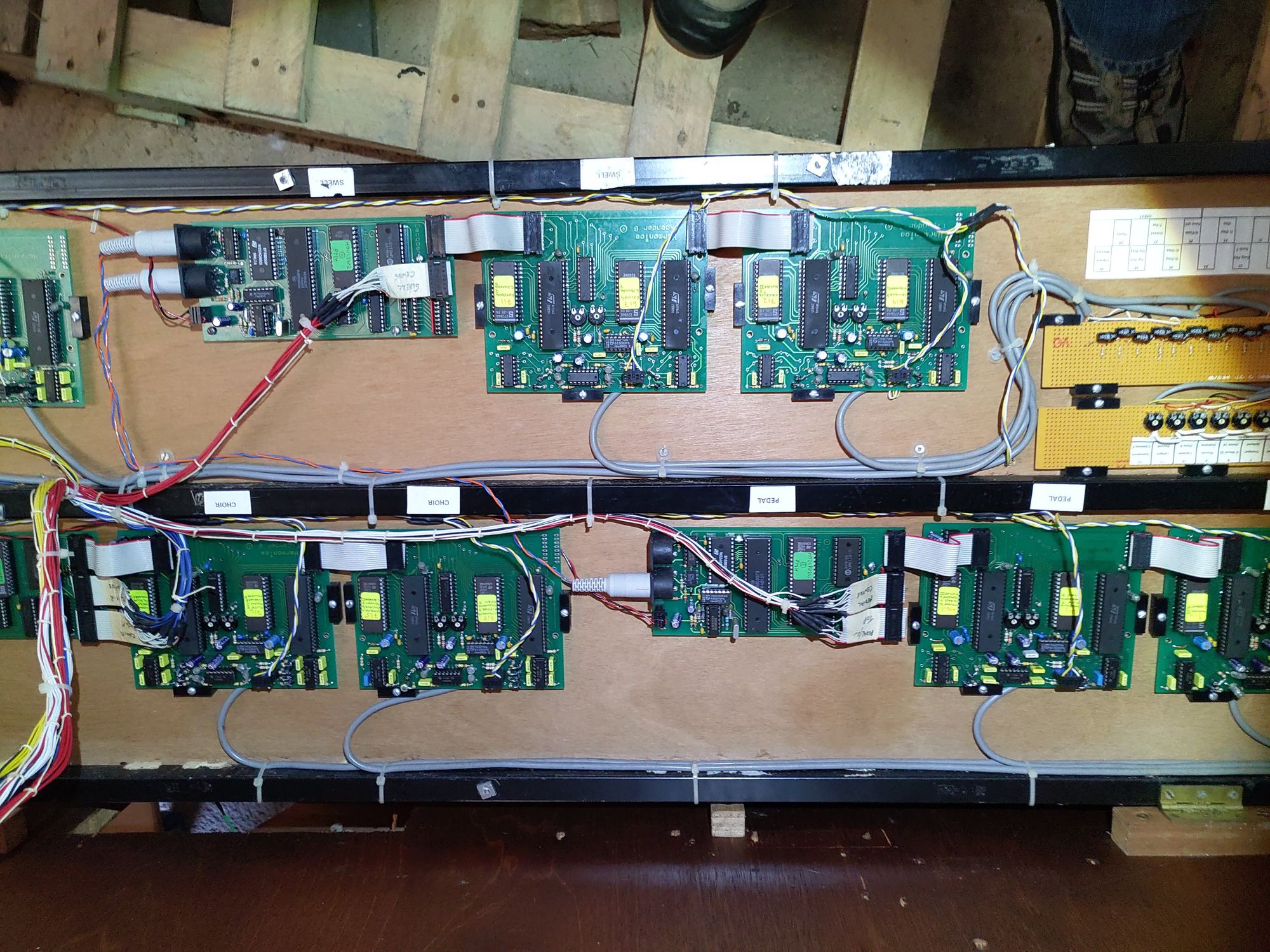
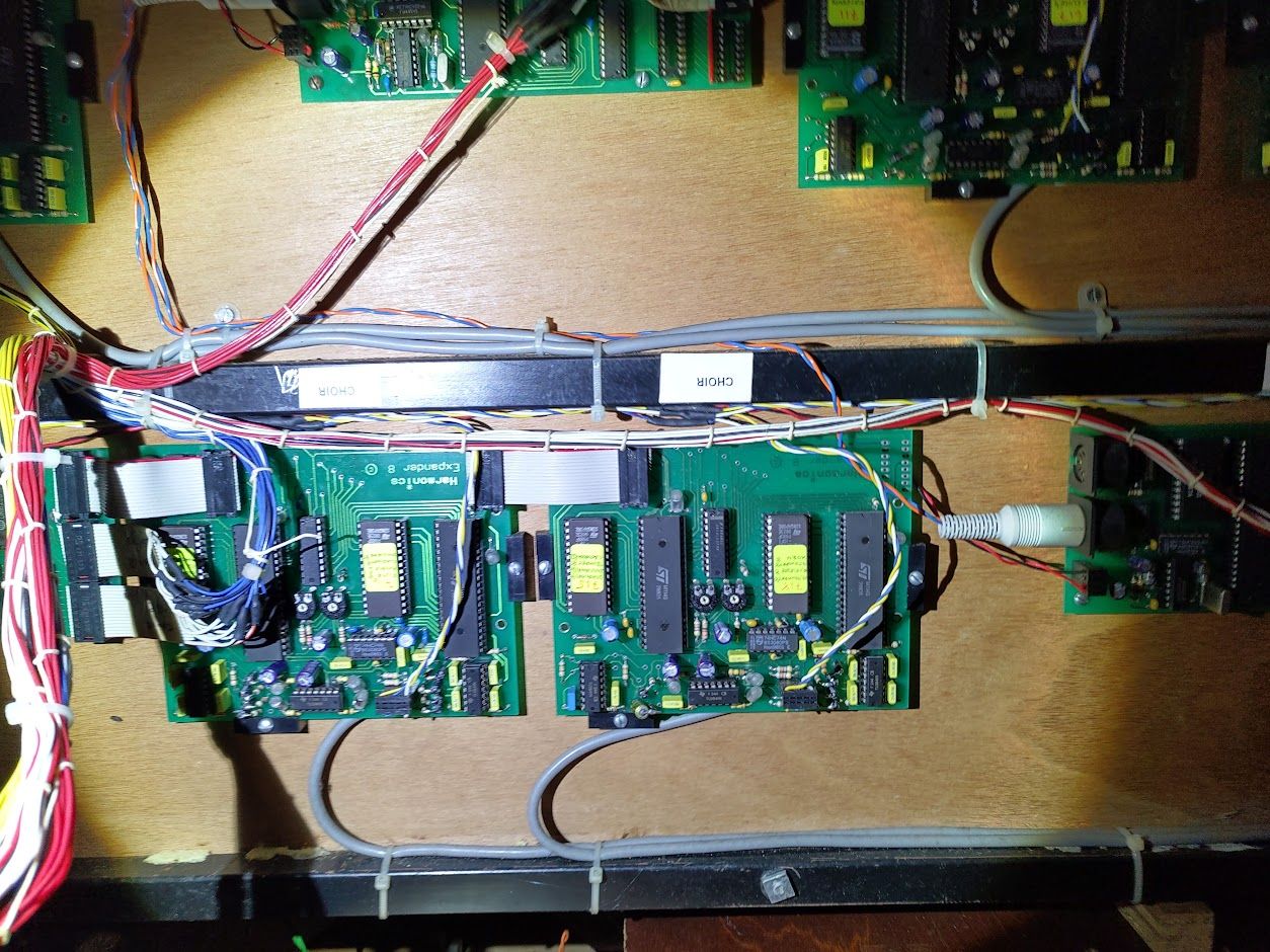
From what I can tell, the MIDI notes come out of the previously mentioned scanner board connected to the manuals and passes through a load of MIDI processor cards. Each card takes in MIDI as well as the current stop positions on a pair of DIP-16 headers; some sort of connection is then passed out onto the actual cards that have the STMicroelectronics M114S digital sound generator chips. These have a associated ROM chip next to them marked with what ranks of pipes they are producing. Presumably, a set of samples exist on these ROMs for each stop type, and are then modified by the M114S along with the MIDI processor card's microcontroller to correctly pitch and time the resultant notes. These then exit the cards on hardwared multicore cabling providing a seperate analog feed for every stop.
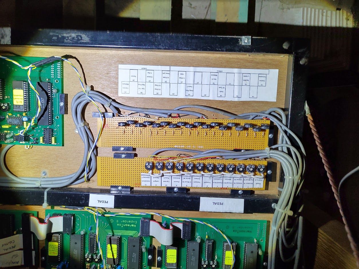
These different stop feeds come together on this rather homemade veroboard mixer with a trim pot to set the volume of each stop individually. The resultant mix then finally passes through another rather homemade looking board and then onto the amplifiers.
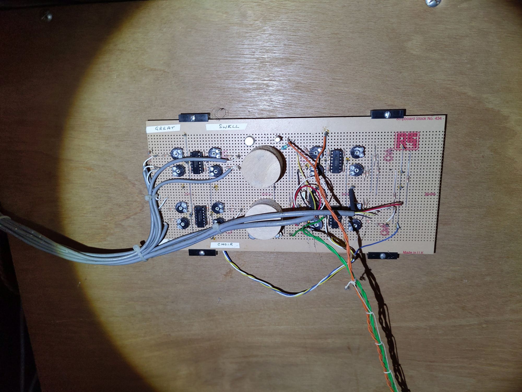
This board, other than the blurry photo, connects to the two expresision pedals in the footwell for controlling the swell and choir. These pedals like on a real organ, control the volume of the enclosed pipes (namely, the pipes in the choir, and pipes in the swell divisions) and allow an analog control over the volume and tonality rather than the usual on-off of organ stops.
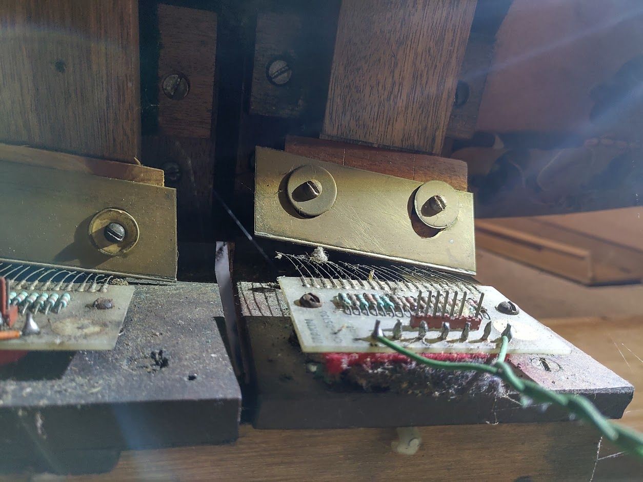
Rather than a potientiometer on these pedals, there is a rather 80's electronic solution to this problem where an angled piece of metal shorts out a ladder of resistors to make a pseudo-continuous different resistance across the final two wires. Definitely a novel solution to a problem that really shouldn't exist seeing as potentiometers have existed for decades! I guess the reliability of this method is a bit higher than a wiper moving around on a carbon path.
Other than the large beefy linear power supplies on each side of the organ, that is mostly all the electronics summed up, so next I'll look at designing the new circuits to MIDI-fy the stops and piston controls.